
Custom Powder Valve Designs for Reliable Bulk Solids Flow Control
2026-10-16
Powder handling often looks easy on paper—until a gate sticks, a seal leaks, or material refuses to discharge evenly. For many plants, the real bottleneck isn't the mixer or the conveyor; it's the valve in between. Custom powder valve designs, like those engineered by AVM, address these hidden flow failures head-on. This article breaks down how tailored geometry, materials, and actuation create reliable bulk solids flow control—and why standard valves so often miss the mark.
Tailoring Valve Internals to Handle Abrasive and Sticky Powders
Powder handling systems often fail not because of the valve body, but because the internals—seats, discs, and seals—were never designed for the specific material moving through them. Abrasive powders like silica or alumina gradually erode standard metal components, while sticky materials such as titanium dioxide or certain food ingredients build up on surfaces, causing jamming and inconsistent flow. The solution starts with material selection: hardened alloys or ceramic coatings for abrasion resistance, and smooth, low-friction polymers or electropolished surfaces to reduce adhesion. Beyond materials, the shape matters just as much. A contoured disc that self-wipes against the seat prevents powder packing, while a reduced dead-space design eliminates pockets where sticky fines can accumulate and harden.
One common mistake is treating valve internals as a one-size-fits-all component. For abrasive service, a rotating disc with a thin edge may cut through powder streams efficiently, but the same geometry becomes a nightmare with sticky powders, which cling to the thin edge and create a snowball effect. Instead, sticky applications benefit from a thicker, rounded disc profile that pushes material away rather than slicing through it. Sealing elements also need rethinking: inflatable or elastomer lip seals work well for dry, free-flowing abrasives, but they can tear or ball up when coated with tacky residue. In those cases, a metal-to-metal seal with a purge port might be more reliable, allowing a controlled gas stream to keep the seating area clean without adding moisture.
Field adjustments often make the difference between a valve that survives a few weeks and one that runs for years. Start by mapping the powder's failure mode: run a simple wear test on a sample coupon, and observe where material accumulates in a transparent test section. Then tailor the internals accordingly—add a harder facing only where abrasion is concentrated, or machine a steeper discharge angle to help sticky powders shed. Don't overlook surface finish; a roughness average of 0.4 micrometers or better significantly reduces adhesion for many hygroscopic powders. Finally, plan for maintenance access: even the best-tailored internals need inspection, so design the valve so that seats and discs can be swapped without removing the entire body from the line.
Geometry Choices That Prevent Arching and Ratholing in Hoppers
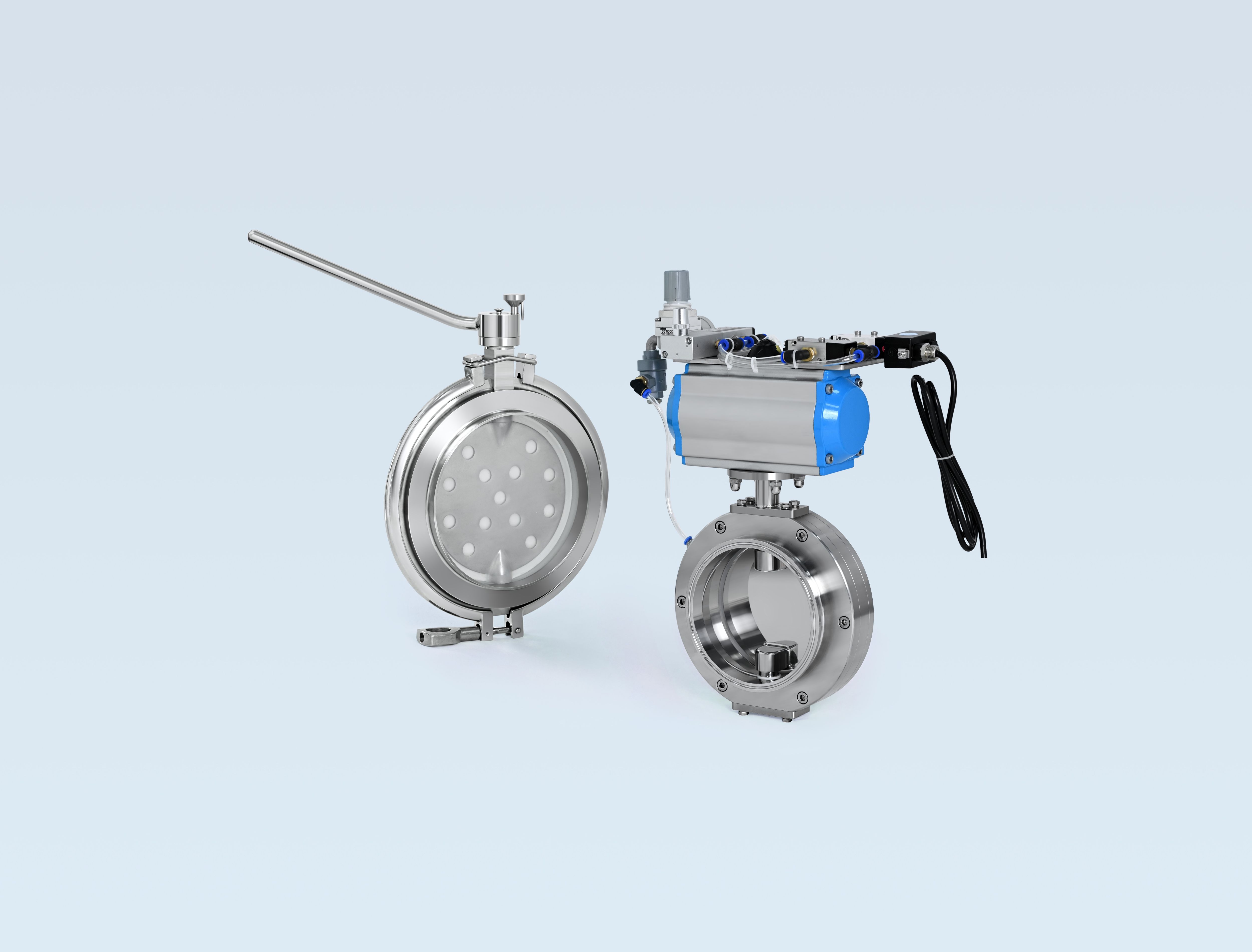
The shape of a hopper does more than hold material; it establishes the flow pattern. Steep, tapered walls matched to the wall friction and internal friction of the stored solid encourage mass flow, where the entire contents move downward. By contrast, shallow angles create funnel flow and leave stagnant zones that can consolidate into ratholes. For many bulk solids, wall angles in the range of 20–30 degrees from vertical work well, while sticky or cohesive materials often require even steeper slopes.
Outlet geometry matters as much as the wall angle. A slotted or rectangular opening breaks cohesive arches more readily than a circular outlet of the same cross-sectional area because the narrow span across the slot is smaller. Increasing the outlet beyond the critical arching diameter—determined through shear testing of the particular material—adds a dependable margin when moisture, temperature, or particle size shifts unexpectedly.
Transitions and corner details are frequent hang-up points. Rounded edges at the inlet-to-cone junction, smooth low-friction liners, and the removal of weld beads or bolt heads all reduce localized friction. In some designs, a curved insert or wedge placed inside the hopper redirects pressure and creates a controlled flow channel, which can prevent both arching and ratholing without increasing the overall bin height.
Why Standard Valve Seats Fail in Fine Powder Service
Standard valve seats are typically machined from solid metal or molded from elastomers, both of which assume a relatively clean contact surface. In fine powder service, particles often measure below 50 microns and can pack into the microscopic gaps between the seat and the closure element. The repeated compression cycle grinds these particles into the sealing face, creating grooves and pinholes that leak even when the valve is fully closed.
Another overlooked factor is the way fine powder behaves under pressure. Unlike larger granules that tend to deflect or crush, fine powders form a nearly incompressible layer that transfers the seating load unevenly. This concentrates stress at random points, causing local deformation of the seat. Once the seat loses its original geometry, the valve must work harder to achieve a seal, which accelerates wear and can lead to premature failure.
In addition, many standard seats rely on a slight interference fit to maintain tight shutoff. With fine powder, the particles act as an abrasive between the mating surfaces every time the valve cycles. Even chemically inert powders like silica or alumina can polish away the seat material over thousands of cycles. The result is a gradual loss of sealing force until the valve no longer isolates the upstream pressure, often without any visible external damage.
Selecting Coatings and Liners for Long-Term Wear Resistance
Material selection starts with a clear picture of the wear mechanism at play. Abrasion from sliding or impact demands a different response than erosion from high-velocity particles, and confusing the two often leads to premature failure. For severe sliding abrasion, chromium carbide overlay plate offers a workhorse solution, while alumina ceramic liners handle fine particle erosion better than most metals. The key is matching hardness and toughness to the specific stress mode, rather than simply choosing the hardest option available.
Installation realities deserve equal weight during selection. A liner that cannot be securely fastened or replaced without excessive downtime quickly erases any performance advantage. Consider modular ceramic tiles with recessed mounting holes for high-wear zones, or trowelable epoxy-based wear compounds for irregular geometries where pre-formed liners leave gaps. Field experience shows that even a small unprotected gap will channel material flow and create a wear hotspot that spreads faster than the original worn area.
Long-term performance also depends on how the coating or liner behaves under thermal cycling and moisture. Polymer liners such as UHMWPE reduce friction and excel in wet, corrosive environments, but they lose dimensional stability above 80°C. Tungsten carbide thermal spray coatings provide excellent erosion resistance at elevated temperatures, though they require careful surface preparation to avoid spalling. Testing candidate materials under actual process conditions for at least three months remains the most reliable way to avoid costly guesswork.
Actuator Sizing for Consistent Discharge Under Variable Head Loads
Sizing an actuator for a tank or reservoir drain that sees varying liquid levels demands more than a single maximum-pressure calculation. As the head drops, the differential pressure across the valve falls, and the force needed to stroke the plug or disc changes along with it. An actuator chosen only for the highest head will often overshoot at low head, making it difficult to hold a stable intermediate opening. One sized for average conditions may not seat tightly or modulate correctly when the level is high. The practical approach is to map the required thrust or torque across the full head range and compare that envelope against the actuator's output curve, leaving enough margin at every point without exceeding its modulation limits.
Consistent discharge under variable head also depends on how precisely the actuator can hold and adjust position. Because the same valve opening produces different flow rates at different differential pressures, the actuator must continuously trim the valve to compensate. Pneumatic spring-diaphragm actuators tend to drift slightly under changing pressure loads due to their lower stiffness, while electric actuators or piston actuators with positioners offer better repeatability. When selecting, check the dead band, hysteresis, and minimum step size. The unit must still resolve small flow changes at the lowest head condition, not just meet the peak thrust requirement.
A useful method is to work backward from the worst-case operating band. Determine the required valve opening range based on the lowest and highest liquid levels, then multiply the valve's torque coefficient at those openings by the maximum differential pressure to find the actuator's rated torque. Add 20 to 30 percent safety factor to cover packing friction, mineral buildup, or light cavitation. Pay attention to stroking speed as well. If the head changes rapidly, the full-stroke time should be less than one-fifth of the level fluctuation period; otherwise, the discharge will lag behind the changing head and fail to provide the intended consistency.
Field-Proven Modifications That Eliminate Powder Flooding and Starving
On a rotary valve feeding a dense-phase conveyor, the real fix wasn't a bigger hopper or a stronger air pulse — it was replacing the flat-bottom bin with a 70-degree mass-flow cone and welding in a series of internal baffles just above the outlet. The baffles broke up the stagnant arch that formed every time humidity crept above 40%, while the steeper cone let the powder slide instead of hang. Within a week, the surge cycles disappeared and the downstream filters stopped clogging with ratholed fines.
For a vacuum receiver that kept choking on fine titanium dioxide, the change that stuck was adding a small vibratory motor to the cone wall and switching the discharge valve from a butterfly to a full-bore pinch design. The vibration only ran for three seconds after each fill cycle, just enough to collapse the aerated pocket without compacting the material. The pinch valve removed the center obstruction that had been throttling the powder and creating the classic flood-then-starve rhythm. Operators noticed the difference immediately — no more manual hammering, no more pressure alarms at 2 a.m.
FAQ
They are built around the specific flow characteristics of a powder, such as particle size, moisture content, and cohesiveness. Standard valves often fail with bridging, rat-holing, or dust leakage, while a custom design tackles those failure modes directly by adjusting internal geometry, seal materials, or actuation speed.
They target bridging and ratholing in hoppers, erratic discharge rates, air in-leakage, and rapid wear from abrasive particles. A properly matched valve can keep even sticky or fragile powders moving at a steady, predictable rate without degradation.
Particle size distribution, bulk density, moisture sensitivity, operating temperature, and pressure differentials. Cohesive or hygroscopic powders may need flexible liners, heated contact surfaces, or non-stick coatings that standard valves simply do not offer.
The wrong metal or polymer can cause galling, corrosion, or product contamination. Food-grade applications often require polished stainless steel, while abrasive minerals demand hardened alloys or ceramic-coated internals to extend service life and maintain seal integrity.
Usually yes. Many designs retain standard flange patterns or compact rotary geometries, but the rotor clearances, seal arrangements, and surface finishes are modified. Retrofitting is often far simpler than replacing an entire conveying or metering system.
Regular checks on seals, bearings, and wear surfaces are critical. Because these valves are built for specific powders, maintenance intervals can be longer, but ignoring small leaks, build-up, or seal degradation quickly leads to flow interruptions and product quality issues.
They reduce dust emissions, prevent cross-contamination between batches, and help maintain inert atmospheres when needed. Tight sealing and controlled discharge also prevent segregation of blended powders, so the final product stays consistent.
Food, pharmaceuticals, chemicals, plastics, minerals, and battery materials. Any process that meters, blends, or conveys powders under challenging conditions can benefit from a valve designed around the actual material behavior.
Conclusion
Valve internals often need a complete rethink when bulk solids include abrasive or sticky materials. Standard seats and seals that work for clean granules quickly cut or bind once fine powder works into the clearance gaps, so custom designs usually open up the passage and add hard-facing or polymer liners where sliding contact occurs. Choosing the right liner is not just about hardness; a tungsten carbide coating can resist erosion but may promote material build-up if the surface finish is too rough, whereas a low-friction polymer might shed sticky product yet wear faster under sharp particles. The internal contour also matters more than most people expect. A gentle, flared outlet instead of a sudden reduction keeps material moving and reduces dead zones where powder can compact.
Hopper geometry upstream of the valve directly influences discharge reliability. Adding a steeper cone or a transition piece with a smooth, polished surface helps prevent arching and ratholing, especially for cohesive powders that gain strength under consolidation. Actuator sizing then has to account for changing head loads: torque or thrust required at full bin is very different from nearly empty conditions, so a properly matched drive prevents both stalled operation and over-travel that can damage the seat. Field experience shows a few simple modifications often solve chronic flooding or starving. A restrictive orifice plate at the outlet, an air injection ring just above the valve, or a revised control sequence that opens the valve only after the feeder reaches speed can stabilize flow without expensive redesign. These practical changes, combined with the right internals and coatings, deliver the kind of dependable powder handling that standard catalogue valves simply cannot match.
Contact Us
Contact Person: Ananda
Email: [email protected]
Tel/WhatsApp: 8619016718200
Website: https://www.wzaomi.com