
Zinc-Nickel Alloy Plating Equipment Manufacturer: What to Look for in High-Performance Systems
2026-09-19
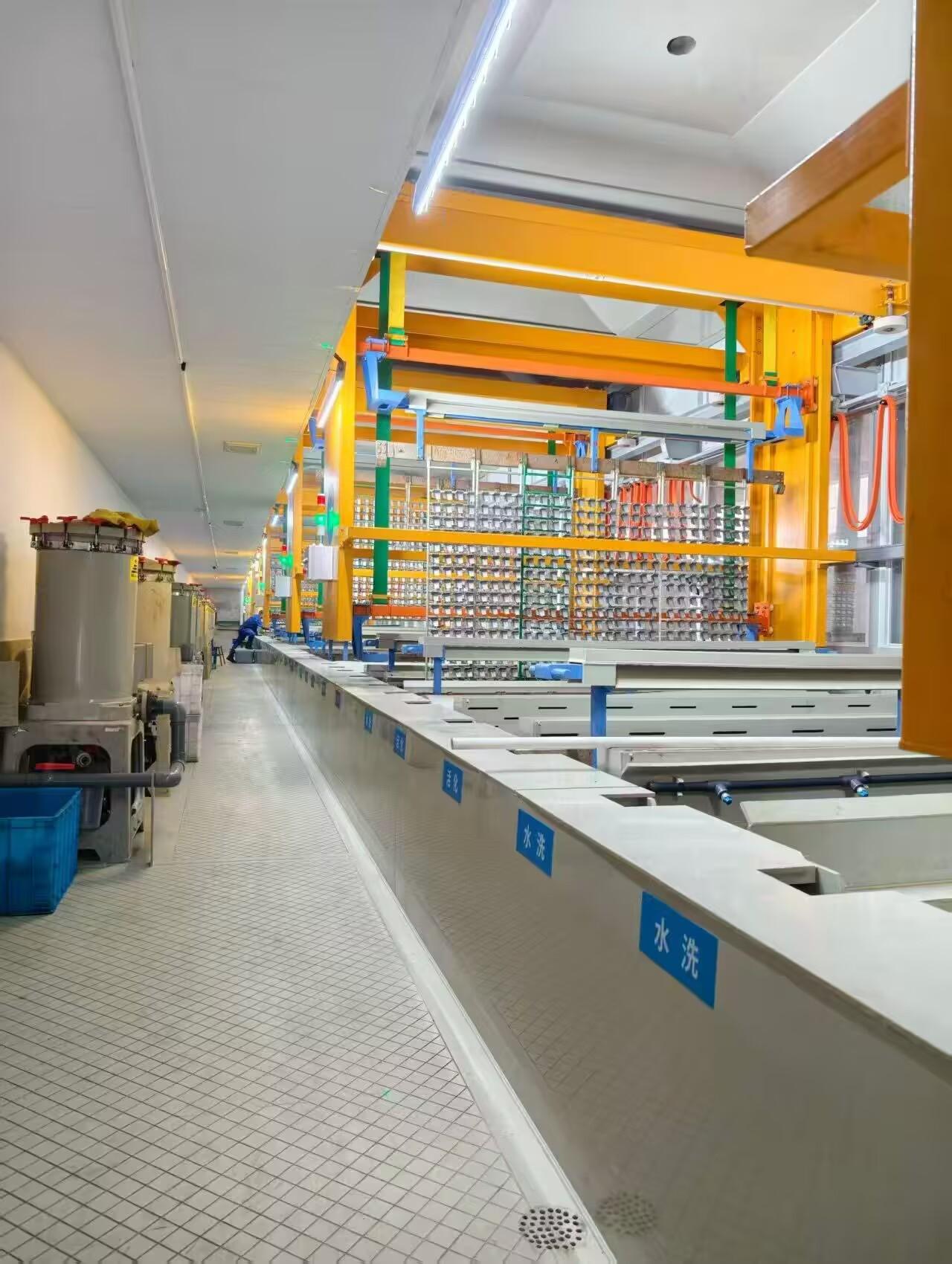
Choosing a zinc-nickel alloy plating line often comes down to one uncomfortable question: will the system hold its bath chemistry, current distribution, and thickness tolerances when production volume climbs? Many equipment catalogs look impressive on paper, yet struggle with edge buildup, anode passivation, or inconsistent alloy ratios once real parts hit the racks. That gap between spec sheets and shop-floor performance is exactly where high-performance systems earn their price. Junda has spent years refining the details that matter most—rack agitation, rectifier ripple, solution filtration, and tank geometry—so plating managers don't have to babysit every cycle. In this post, we break down the features worth prioritizing before you sign off on your next zinc-nickel line.
Bath Chemistry Control: Where Most Zinc-Nickel Lines Fall Short
Maintaining the zinc-to-nickel ratio within a tight window is where many plating lines quietly lose control. Operators often rely on infrequent manual titrations or assume that rectifier settings alone will keep the deposit composition stable. In reality, anodes dissolve at different rates, drag-out shifts the metal balance, and temperature swings alter plating efficiency. Without real-time or at least shift-based monitoring of both metals, the bath drifts toward higher zinc content, producing dull, brittle deposits that pass initial thickness checks but fail corrosion testing.
The additive package creates a second layer of instability. Brighteners, complexants, and wetting agents are consumed not only by electrolysis but also by oxidation at insoluble anodes and by drag-out. Many systems dose based on amp-hours alone, ignoring the fact that additive breakdown accelerates as the bath ages or when the temperature climbs above the recommended range. The result is a bath that looks fine on a titration sheet but behaves differently on the parts, with edge burning or poor low-current-density coverage appearing long before the next full analysis.
Impurity buildup is the slow killer that gets overlooked until rejects appear. Zinc anodes introduce trace lead, cadmium, or copper unless high-purity feedstock is enforced. Iron from poorly maintained racks or fallen parts accumulates and interferes with the nickel deposition reaction. Carbonate buildup in alkaline systems from air exposure also shifts the operating window. Most lines lack a routine for targeted impurity removal, relying instead on dumping the bath when problems become visible. That reactive approach costs far more than preventive purification and often hides the real source of failure.
Pulse Plating vs. DC Rectifiers: Does It Actually Change Your Alloy Ratio?
With a conventional DC rectifier, the alloy ratio is mostly locked in by bath chemistry and cathode current density. You can tweak the solution, but once the rectifier is humming along, the deposition potential for each metal shifts only with agitation or temperature. This makes it surprisingly hard to push a nickel-cobalt or zinc-nickel deposit away from its natural composition.
Pulse plating changes the game not by adding new metals, but by altering how ions arrive at the surface during each on/off cycle. A short, high-current pulse can momentarily deplete the more noble metal near the electrode, forcing a brief shift toward the less noble component. When the pulse relaxes, fresh solution floods back in, and the next cycle repeats that bias. Over hundreds of cycles, this can produce an alloy ratio that would be impossible with a steady DC signal at the same average current density.
That said, the effect is not universal. In some alloy systems, especially those with similar deposition potentials or strong complexing agents, pulse parameters barely move the ratio by more than a percent or two. In others, adjusting peak current density, pulse duration, or duty cycle can swing the composition by ten points or more. The real answer is that pulse plating gives you an extra set of control knobs, but whether they actually turn the alloy ratio depends on the specific metal pair and electrolyte.
Anode Configuration and Racking Design: The Overlooked Variables in Coating Uniformity
In most coating lines, attention goes to bath chemistry, voltage, and dwell time. But the physical arrangement of anodes and the way parts are racked quietly dictate whether a coating builds evenly or leaves thin edges and burnt highlights. Two identical tanks with the same chemistry can produce radically different results simply because one has anodes clustered near the tank walls while the other uses a distributed pattern matched to part geometry. The distance from anode to cathode surface, the total anode area relative to workload, and the presence of auxiliary anodes in recessed zones all shape local current density. Ignoring these variables means chasing pH and additive levels while the real culprit is a poorly balanced electrical field.
Racking design multiplies these effects. Part orientation on the rack controls which surfaces face the anodes, how solution drains, and whether trapped air or gas bubbles create voids. A dense rack may improve throughput but can create shielding, where outer parts steal current from inner ones. Rotating or repositioning parts between coats sometimes matters less than simply moving rack hooks or redesigning contact points to reduce resistance. Throwing power, the ability to coat recessed areas, is not just a property of the bath; it is heavily influenced by how far the anode sits from the recess and whether the rack allows sufficient current to reach that zone without overplating the nearest edge.
The practical fix starts with mapping current distribution rather than assuming a uniform tank. Simple trials with test panels at different rack positions can reveal consistent low-build or high-build zones. Adjusting anode spacing, adding conforming anodes along complex profiles, or changing rack density from, say, 40 to 30 parts per bar often improves uniformity more than a 10% increase in voltage or additive concentration. Treating anode configuration and racking as first-order variables, not afterthoughts, turns coating uniformity from a recurring headache into a controllable outcome.
Rinse Water Recovery and Waste Treatment: The Hidden Cost of High-Performance Plating
Plating lines rarely show the true price of their rinse stages on the quote sheet. High-performance coatings demand aggressive chemistries, and every drag-out carries metal ions, brighteners, and wetting agents into the rinse tanks. Operators often treat this water as a simple overflow problem, but the real expense hides in what happens after it leaves the floor. Recovery systems, ion exchange columns, and evaporators all need constant attention, and their maintenance schedules rarely match production peaks. When a line pushes for higher throughput, the rinse water volume spikes quietly, dragging down efficiency long before a compliance issue appears.
Waste treatment adds another layer that accountants struggle to model. Sludge from hydroxide precipitation is heavier than expected because co-precipitated additives and chelators bind extra mass. Filter presses clog on unpredictable cycles, and the labor to manage them never shows up as a line item. Some shops try to sidestep this by sending concentrated rinses off-site, but the hauling fees and manifests create their own paperwork burden. The hidden cost is not the chemicals themselves; it is the time spent troubleshooting pumps, adjusting pH probes, and waiting for a settling tank to clear enough to discharge.
A smarter approach starts with drag-out reduction at the source. Slower withdrawal speeds, longer drip times, and air knives can cut the rinse load by half before treatment even begins. Recovering metals from the first rinse with a dedicated electrolytic cell often pays back faster than adding more treatment capacity. But the real shift is cultural: when production managers see rinse water as a process stream rather than a waste stream, the hidden cost stops hiding. Every gallon recovered means less sludge to haul, fewer filter changes, and a plating line that runs closer to its actual capability.
Why Nameplate Capacity Misleads: Calculating Real Throughput for Your Part Geometry
The number printed on a machine's nameplate rarely survives contact with your actual part. That figure assumes a clean, straight-line motion at maximum feed rate—no tight corners, no rapid directional changes, no toolpath interruptions. But real parts have pockets, contours, drilled holes, and tiny radii that force the machine to slow down, accelerate, and sometimes pause entirely. The result is a true throughput that can be half—or less—of what the nameplate promises.
Calculating real throughput starts with your geometry, not the machine's marketing sheet. Break the toolpath into segments: long straight runs where feed rate can stay high, versus short arcs and sharp corners where acceleration limits kick in. Use your CAM software's cycle time estimate, but validate it against the servo tuning parameters—jerk, acceleration, and corner rounding. Even a small radius can trigger a speed clamp that cascades across the entire operation. The real cycle time is the sum of each segment's duration, including all accel/decel phases, not just the cutting distance divided by nameplate speed.
For a practical example, consider a 100 mm square pocket with 2 mm corner radii. At 10,000 mm/min nameplate feed, the straight walls can use that full speed, but each corner forces a drop to perhaps 1,500 mm/min for a few milliseconds. Four corners per pass, ten passes deep—suddenly those milliseconds become seconds, and the job runs 40% longer than a naive calculation. The fix isn't a faster machine; it's smarter toolpath geometry—larger radii where possible, or spiraling entries that maintain constant velocity. Match your part geometry to the machine's dynamic envelope, and the real throughput emerges from the math, not the label.
What a Manufacturer’s Test Lab Should Prove Before You Commit to a System
A manufacturer’s test lab isn’t just a room with equipment—it’s the place where claims meet reality. Before you sign off on any system, you need to see evidence that the lab has pushed components beyond their rated limits, cycling them through thermal stress, vibration profiles, and continuous load scenarios that mirror your worst operating days. Ask for raw data logs, not just summary slides. If they hesitate to share failure reports or test-to-destruction results, treat that as a red flag.
Real validation goes further than a spec sheet check. The lab should demonstrate how the system behaves when one part degrades or a power rail sags mid-operation. Watch for tests that simulate brownouts, signal noise, and unexpected shutdown sequences. A good manufacturer will walk you through their fault-injection methods and show you how the system recovers without corrupting state or requiring a manual reset. If the lab can’t reproduce edge cases on demand, the product hasn’t been proven—it’s been assumed.
Finally, pay attention to how the lab communicates uncertainty. Mature engineering teams publish tolerance ranges, environmental derating curves, and life expectancy under different duty cycles. They don’t hide behind phrases like “industry standard” or “proven in the field” without context. The lab should be able to explain which failure modes they explicitly tested against and which ones remain open risks. That level of honesty is what separates a vendor who wants your long-term trust from one who just wants your purchase order.
FAQ
Look for suppliers that offer current density mapping or modeling based on your specific rack or barrel loading. Ask for a documented uniformity trial using actual production parts, not just flat test panels. Check whether the rectifier can independently control current to segmented anodes or auxiliary anodes; this is what separates lines that hit ±1.5 μm spread from lines that hide behind vague 'good coverage' claims. Also request data on edge buildup and low-current-density areas because those are the usual failure points for corrosion resistance.
You need a rectifier with tight ripple control, preferably under 5% at full load, and fast response for pulse or pulse-reverse operation if your alloy ratio drifts. Look for multiple channel outputs when running mixed part sizes in one tank, plus digital logging of voltage and current per station. A unit that only supplies constant current without waveform flexibility will limit your ability to control nickel content in the 12-15% range where the alloy performs best.
For acid zinc-nickel, use insoluble anodes with dedicated anode membranes to keep anode sludge out of the bath and reduce nickel carbonate buildup. Polypropylene or PVDF tank liners should be thermally welded, not glued, and the tank should include a secondary containment tray. Ask for anode isolation valves and separate rinse compartments so that drag-out is captured before it hits the floor. This keeps bath chemistry stable and cuts monthly maintenance hours.
It is not a luxury; it is the only reliable way to hold nickel content within a tight window. Manual titration once per shift will drift enough to move the alloy ratio outside 12-15%, changing corrosion performance and appearance. Look for an analyzer that measures zinc, nickel, and pH at set intervals—or better, continuous sampling—and links to metering pumps for brightener and caustic. Remote alerts and data logging are also worth specifying if you run multiple shifts.
Exhaust must be designed for both acid mist and hydrogen, with capture velocity over the tank surface high enough to prevent fumes from entering the work area. The waste treatment side should include segregated rinse waters, so high-cyanide or chelated streams don't mix with dilute rinses. Ask for a closed-loop rinse system or at least ion exchange recovery for nickel, because discharge limits are getting tighter and retrofitting later costs more than specifying it upfront.
Standard lines often fail on racking density, anode placement, or rectifier sizing because they are built around general-purpose plating, not the unique current distribution needs of zinc-nickel. High-performance systems usually require at least some customization: longer plating tanks to reduce current density at a given production rate, automated hoists with precise dwell timing, and anode spacing matched to your part profile. Insist that the manufacturer modify the line around your parts rather than forcing your parts into their catalog design.
Run a full production trial with your real parts, not samples supplied by the manufacturer. Measure thickness at a minimum of five points per part, then perform salt spray or cyclic corrosion testing to verify the expected hours to red rust for your alloy composition. Check bath temperature stability during a continuous shift, not just a one-hour test. Also verify rectifier ripple and waveform under maximum load, because some suppliers will certify a unit on paper but fail under actual tank resistance.
Compare energy consumption per square foot plated, not just rectifier kW rating. Ask for chemical consumption estimates based on your production volume and drag-out rates. Include anode replacement or membrane maintenance, rinse water treatment, and labor hours for bath control. A cheaper line that needs more manual titration, more frequent bath dumps, and higher reject rates will cost more within two years than a properly automated system.
Conclusion
A zinc-nickel line only performs as well as its least-controlled variable, and in most shops that variable is the bath. You can buy the most expensive rectifier on the market, but if the chemistry drifts outside a narrow window—pH, temperature, brightener breakdown, zinc-to-nickel ratio—the deposit will shift from 12–15% nickel to something closer to 6% or 20%, and neither will pass salt spray. Pulse plating versus DC isn't a marketing checkbox; it changes how nickel and zinc deposit because their reduction potentials differ, so pulse parameters can push the alloy ratio one way or the other. But that only matters if the anode arrangement and racking design let current reach every part surface evenly. Too many lines hang parts too close to anodes, use generic racks, or ignore anode passivation, and then wonder why the coating thickness varies by 30% across a single load. A high-performance system has to treat bath control, rectifier waveform, and anode-to-part geometry as one problem, not three separate purchases.
The hidden cost of a zinc-nickel line usually shows up in rinse water and waste treatment, not in the plating tank itself. If you're not recovering drag-out and recycling rinse water back into the bath, you're paying to treat nickel-bearing wastewater and buying more nickel salts than necessary. A well-designed system includes a closed-loop rinse arrangement or at least an ion-exchange recovery step, and that changes the operating cost per square foot more than any rectifier upgrade. Then there's the nameplate capacity trap: a manufacturer may list a line as 500 racks per hour, but if your parts are deep-draw tubes or have blind holes, real throughput can be half that. You need to calculate plating time based on current density at the lowest-current-density area of your specific part geometry, not a flat panel. Before committing, ask the manufacturer's test lab to run your actual parts—or at least a representative sample—and prove the alloy ratio, thickness distribution, and corrosion resistance under your production conditions. If they won't do that, the spec sheet is just a wish list.
Contact Us
Contact Person: hayyr
Email: [email protected]
Tel/WhatsApp: 8613082110525
Website: https://www.jundaelectroplating.com